
How Do You Troubleshoot Common Faults in Industrial Transformers?
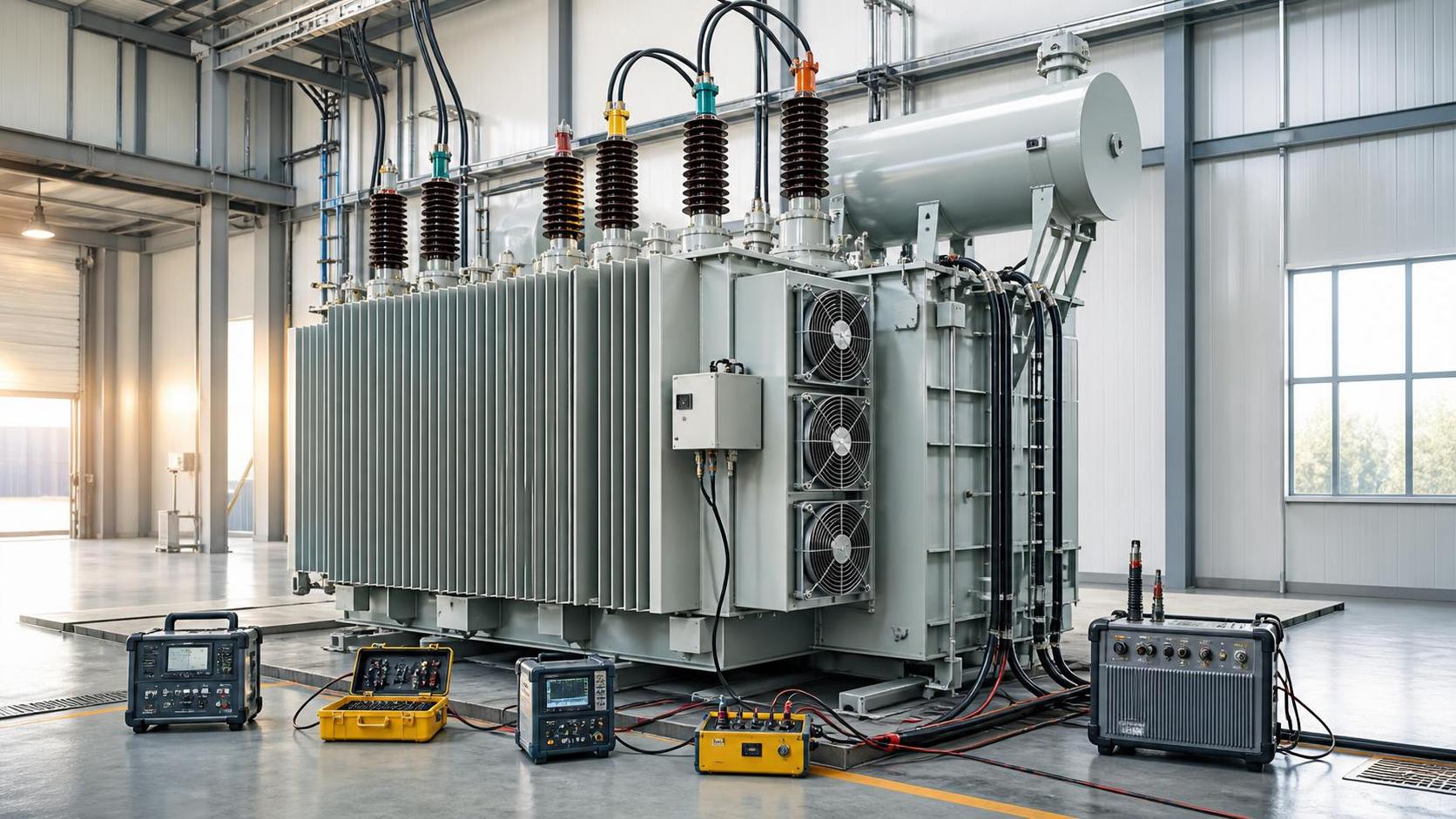
Industrial transformer faults should be approached as a condition-assessment problem rather than a single-component repair. A high temperature alarm, humming sound, oil stain, or unstable secondary voltage may originate inside the transformer, but it may also be caused by overload, poor ventilation, loose connections, unbalanced loads, harmonic distortion, or an upstream switching event. Isolate the equipment under the applicable electrical safety procedure before opening panels, removing covers, or taking contact measurements. Record the operating condition before power is removed: load level, ambient temperature, tap position, alarm history, cooling equipment status, and the timing of any process disturbance.
A useful troubleshooting sequence begins with visible evidence, then compares electrical and thermal measurements against the transformer nameplate, drawings, previous maintenance records, and the actual connected load. Avoid changing tap settings, tightening energized terminals, or adding oil simply to clear an alarm. Those actions can obscure the original fault and create a more serious failure path.
Start with the operating symptoms
Document the fault as precisely as possible. “Transformer is hot” is not enough to identify a cause. Note whether the temperature indication is from top oil, winding simulation, a thermal sensor, or an infrared scan. Determine whether the rise occurs only during a particular production shift, after a motor starts, during furnace operation, or continuously at a modest load. A transformer that heats only under peak process demand may have a loading or cooling issue, while one that remains hot at light load may have a circulating-current problem, poor connection, internal loss, or an incorrect temperature indication.
For voltage complaints, measure all phase-to-phase and phase-to-neutral values where a neutral is present. Compare the primary voltage, secondary voltage, and voltage at the load terminals. A normal transformer secondary voltage with low voltage at a distant machine points toward cable sizing, joints, contactors, busbar connections, or voltage drop downstream. A persistent imbalance across transformer terminals requires closer examination of phase loading, winding condition, tap connections, and supply quality.
Before interpreting any reading, confirm that the instrument is suitable for the system voltage and waveform. Non-sinusoidal loads can mislead basic clamp meters and voltage meters. Variable-speed drives, rectifiers, welders, and large electronic power supplies may introduce harmonics that raise transformer losses and affect ordinary current measurements.
Overheating and repeated temperature alarms
Overheating is often blamed on transformer size, but heat must be traced to a source. Begin by comparing actual current on each phase with the rated current. Use a sufficiently long observation period if the connected process cycles. One phase can be heavily loaded even when the total apparent load seems acceptable. On a three-phase transformer, unequal phase currents can increase winding losses and create localized heating.
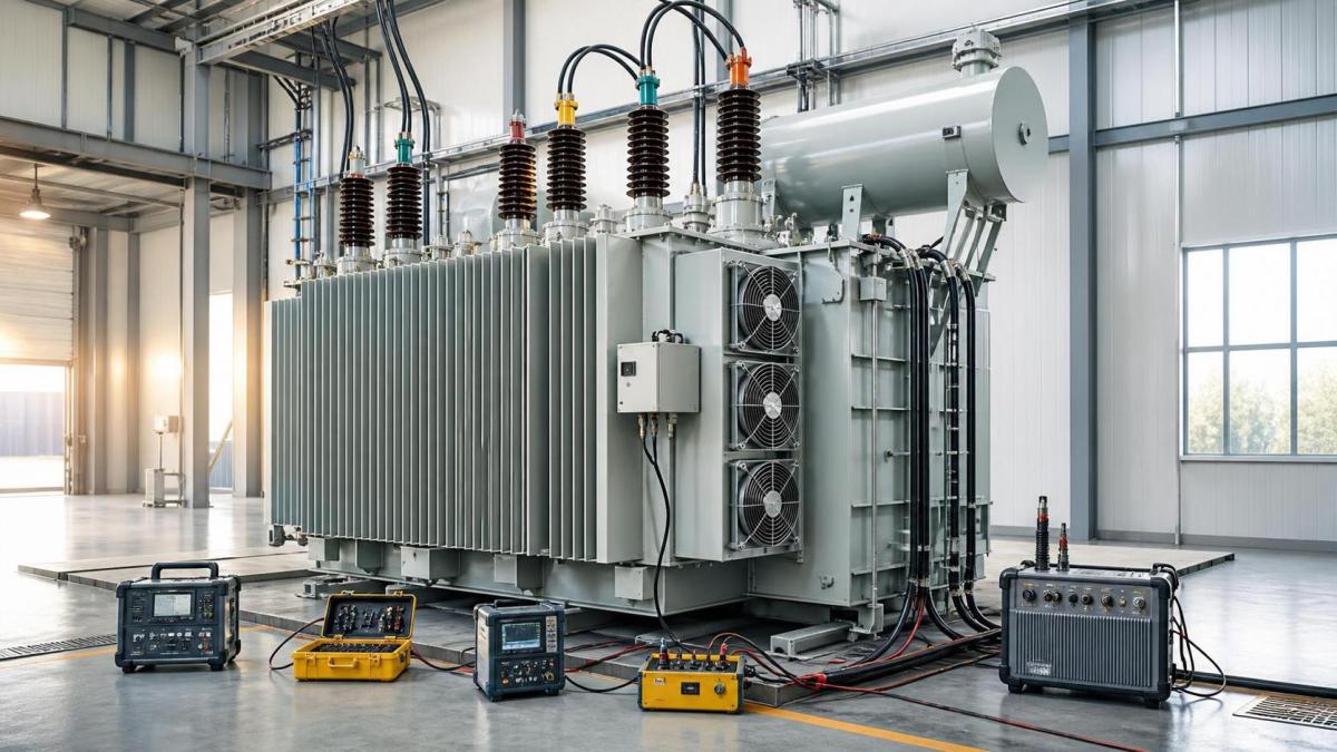
Then inspect the cooling path. Dry-type units require clear air passages through winding ducts and around enclosure openings. Dust, fibers, oil mist, packaging debris, or blocked louvers restrict heat transfer. Confirm that forced-air fans start at their intended temperature stage, rotate in the correct direction, and are not obstructed. A failed fan relay, damaged thermal switch, disconnected control supply, or seized bearing can leave the transformer operating without the cooling mode assumed by its rating.
Oil-filled transformers need a different review. Check oil level, gauge condition, radiator valves, cooling fans or pumps where fitted, and signs of restricted radiator circulation. A low oil level can expose active parts or reduce cooling performance, but adding oil without finding the cause of the loss is poor practice. Inspect gaskets, valve stems, bushings, radiator flanges, and weld areas for seepage. The oil type and handling method should match the equipment documentation; mixing unsuitable fluids or introducing moisture during topping-up can create further insulation problems.
Thermal imaging is useful when performed under meaningful load. Scan bushings, cable lugs, busbar joints, tap-changer compartments, cooling connections, and enclosure vents. A concentrated hot spot at one termination usually suggests high resistance from poor contact pressure, oxidation, damaged strands, or an incorrectly installed lug. A broadly warm tank or enclosure may be normal under load, so compare similar phases and similar components rather than judging temperature from one image alone.
Where load and cooling appear normal, investigate harmonic loading. Harmonic currents raise eddy-current and stray losses, particularly in windings and metallic structural parts. Review power-quality records or use an appropriate analyzer at the transformer secondary. A transformer selected for conventional linear loads may run hotter after additional drives, UPS equipment, or rectifier loads are connected, even when the fundamental current remains within expectation.
Insulation deterioration, low resistance, and moisture concerns
Insulation faults can develop slowly through heat, moisture, contamination, mechanical movement, or electrical stress. Warning signs may include a declining insulation-resistance trend, repeated protection operation, unusual dissolved-gas results in oil-filled equipment, visible tracking near bushings, or a burnt odor after an event. A single insulation-resistance value is less informative than a properly recorded trend taken with the same test voltage, comparable temperature conditions, and a consistent test method.
Disconnect or isolate external circuits as required before insulation tests. Connected surge protectors, controls, meters, capacitors, and electronic equipment may be damaged by an insulation tester or may distort the result. Measure winding-to-earth and winding-to-winding insulation according to the equipment arrangement. Allow sufficient discharge time after testing; transformer windings store energy and must be discharged safely before reconnection.
Low readings do not automatically prove winding failure. Condensation in a dry-type enclosure, dirty bushing surfaces, wet terminal boards, cable contamination, or temporary humidity can reduce readings. Inspect for water ingress through damaged gland plates, roof leaks, open conduit entries, failed enclosure seals, and poorly protected outdoor terminations. If moisture is suspected in an oil-filled transformer, oil sampling and laboratory analysis may be needed before deciding whether filtration, drying, repair, or further internal inspection is appropriate.
Visible carbon tracking around a bushing is a serious clue. Clean surface contamination only after the equipment is safely isolated, but do not assume cleaning resolves the issue. Examine for cracked porcelain or polymer insulation, loose hardware, damaged stress-control components, and evidence of partial discharge. Any suspected internal insulation breakdown, flashover, or abnormal gas formation warrants controlled investigation rather than repeated energization attempts.
Abnormal noise, vibration, and mechanical movement
A steady low-frequency hum is normal for many transformers, especially as load changes. Troubleshooting begins when the sound becomes louder than its normal baseline, intermittent, metallic, crackling, or accompanied by vibration in panels, radiators, or bus ducts. Record when the noise occurs and whether it follows changes in voltage, load, fan operation, or nearby machinery.
Loose enclosure panels, core clamps, mounting bolts, cable supports, and radiator hardware can amplify normal magnetostriction. With the transformer de-energized, inspect mechanical fasteners and supports for looseness, corrosion, or fatigue. Do not tighten internal core or winding clamping hardware without the manufacturer’s procedure, because incorrect torque or disturbance of insulation structures can create damage.
A pronounced hum at no-load can be associated with excessive supply voltage, incorrect tap position, or magnetic saturation. Confirm the primary voltage against the rated tap voltage and verify the tap changer position. Tap links and off-circuit tap selectors must only be changed in the fully de-energized condition specified for the unit. If an on-load tap changer is fitted, inspect its control indications, operation counter, motor-drive condition, and maintenance record before assuming that the main transformer winding is at fault.
Crackling, popping, or intermittent snapping is more urgent than ordinary hum. It can indicate arcing at a connection, contamination at a bushing, deteriorated insulation, or a fault in associated switchgear. Remove the transformer from service where the protection scheme and operating procedure require it, then inspect the connected equipment as well as the transformer itself.
Oil leaks and oil-condition warning signs
Small oil stains should be traced, cleaned, and monitored rather than ignored. Leakage at a gasket may be caused by aged sealing material, uneven bolt loading, flange distortion, thermal cycling, or excessive internal pressure. Leakage around a bushing can also indicate a sealing problem or a damaged component. Mark the area after cleaning and inspect it after normal temperature cycles to distinguish an active leak from residue left by an earlier repair.
Oil appearance alone is not a reliable diagnostic method. Darkening may result from aging, while clear-looking oil can still contain moisture or dissolved gases. A representative oil sample requires clean, dry sampling equipment and a point that avoids collecting settled debris or contaminated external residue. Sample labeling should include transformer identification, date, operating status, and any recent abnormal event. Without that context, later results are difficult to compare.
Do not open a transformer tank merely because an oil test is abnormal. Review the type of result, trend history, load condition, and protection records. Certain patterns may justify further electrical tests, inspection of bushings or tap-changing equipment, oil processing, or specialist internal examination. Repeated energization after a suspected internal arcing event can worsen damage.
Voltage instability and protection trips
When output voltage appears unstable, separate a transformer problem from a supply or load problem. Measure voltage at the primary terminals, transformer secondary terminals, and the affected distribution point. A voltage dip that begins at the primary is generally upstream of the transformer. A dip only at the remote load may come from a long feeder, poor joint, undersized conductor, failing contactor, or high starting current from motors and compressors.
Protection trips must be investigated from the relay target, event record, fuse condition, and breaker status rather than from the trip alone. An overcurrent trip can result from overload, downstream short circuit, inrush, incorrect protection settings, or internal winding damage. Differential, earth-fault, pressure, gas, or temperature alarms carry different implications and should not be reset as a routine response.
- Compare the event time with process changes, switching operations, and utility disturbances.
- Inspect secondary cables and connected distribution equipment for short circuits, water ingress, damaged insulation, or burned terminations before declaring the transformer defective.
- Review protection settings after any change in transformer rating, impedance, tap arrangement, parallel operation, or major load addition.
- Where transformers operate in parallel, confirm matching vector group, voltage ratio, tap position, impedance characteristics, and phase sequence. Mismatches can produce circulating current and overheating even without a large external load.
Connections, bushings, and external components
Many apparent transformer failures are found at the interfaces around it. Inspect cable lugs for discoloration, loose bolts, strand damage, incompatible metals, inadequate compression, and signs that aluminum conductors were terminated without suitable preparation. Copper and aluminum connections require attention to contact surfaces, approved compounds where specified, hardware selection, and torque values. Over-tightening can damage terminals; under-tightening creates resistance heating.
Examine bushings for cracks, contamination, chipped insulation, loose terminals, and moisture paths. Outdoor units need particular attention after severe weather, washdown exposure, or airborne industrial contamination. Grounding conductors, neutral connections, surge arresters, temperature sensors, fan circuits, and alarm contacts should be inspected as part of the same fault investigation. A failed auxiliary component can cause a transformer alarm without indicating an internal electrical defect.
Return-to-service discipline
Before re-energization, remove temporary grounds and test leads, restore covers and barriers, verify the intended tap position, confirm correct phase identification, and ensure all tools and loose materials have been removed. Record measured values, observed defects, corrective work, replacement parts, oil additions, torque records where applicable, and any test limitations. This record turns the next abnormal reading into evidence rather than another isolated incident.
Persistent overheating, suspected internal insulation damage, unexplained gas or pressure alarms, repeated differential protection operation, or fault evidence inside the tank should be escalated for detailed diagnostic work. A transformer can appear serviceable after a reset while an internal defect continues to develop. Controlled testing and repair planning are generally preferable to allowing a minor indication to become an unplanned outage.
Related Intelligence